
RECENTLY CHECKED
All projects →
CAIBI ASSESSMENT

SmartKnob

CAIBI VERDICTBUILD FOR THE EXPERIENCE

An open haptic control knob that uses a brushless gimbal motor and magnetic encoder to create software-defined detents, endstops, springs and other tactile behaviours.

Build or buy?

Compare the documented build with the purchase reference.

Build it yourself

Known parts cost£74–£148Build total not establishedCreator allowance; complete BOM total not tallied
Time
Time-consuming advanced build
Difficulty
5/5
Physical processes
PCB fabrication · SMD soldering · 3D printing · ESP32
See build requirements →

Purchase reference

Buy price referencePrice not checkedNo priced alternative recorded

Check the source for the exact model, availability and what is included.

Check comparison evidence →
Purchase comparison not yet priced
What the prices cover

The creator explicitly says the total is not yet fully tallied, but estimates a single build is probably under $200 and likely around $100 to $150 depending on fabrication and minimum-order quantities.

Includes: PCB/electronics; Motor/display; Printed mechanical parts.

Not included: Advanced soldering/rework tools; Minimum-order waste; Shipping from multiple suppliers.

Build evidence recorded 4 Sep 2026. Currency conversions are approximate.

SmartKnob is primarily an open haptic input platform. Consumer knobs and dials do not provide a sufficiently similar mechanical, haptic and development surface for a savings claim.

BUILD AT A GLANCE

Source view and main parts

Check the source ↗
SmartKnobSmartKnob · Scott Bezek ↗
PHYSICAL BUILD8 key parts or groups
No.Source specification
01Base PCB
02Screen PCB
03ESP32 control electronics
04Motor driver and angle sensor
05Hollow-shaft gimbal motor
06Round LCD and watch glass
07Precision printed mechanics
08Soldering and assembly supplies
Full source specifications
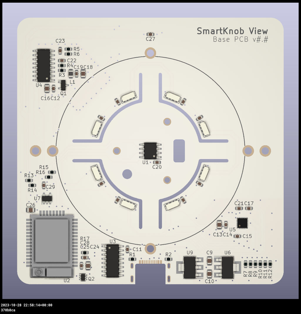
  1. SmartKnob View base PCB, ordered at the specified 1.2 mm thickness with white solder mask
  2. SmartKnob screen PCB, also specified at 1.2 mm thickness
  3. ESP32-PICO-V3-02 based control electronics and very small-pitch surface-mount components
  4. TMC6300 motor driver and magnetic angle-sensing hardware from the stable BOM
  5. Recommended hollow-shaft brushless gimbal motor
  6. 240 x 240 GC9A01 round LCD and 39.5 mm watch glass
  7. Six precision printed mechanical parts, preferably from the stable mechanical release
  8. Solder paste, stencil, hot-air or reflow equipment, flux, microscope or strong magnification, and fine assembly tools
TOOLS / PROCESSES4 involved
  • PCB fabrication
  • SMD soldering
  • 3D printing
  • ESP32
The real-world workYOU STILL HAVE TOThe real-world work
  • Order PCBs and parts
  • Reflow or hot-air solder fine-pitch components
  • Print precision parts
  • Assemble motor and display
  • Calibrate and debug hardware
THE BUILD SEQUENCE

How it comes together

1Preparation

  1. Choose stable artifacts before ordering

    Do not order from the auto-generated master BOM and Gerbers simply because they are newest. The creator labels those artifacts untested and directs builders to tested release assets for stable hardware.

    AI + YOU
  2. Order the two PCBs and precision parts

    Order the base and screen boards at the documented 1.2 mm thickness, source the recommended motor and electronics, and print or outsource the six mechanical parts. The published examples use MJF nylon where tight tolerances and surface finish matter.

    YOU
  3. Assemble the fine-pitch electronics

    Populate the base and screen PCBs using a stencil, reflow or hot air where appropriate. The TMC6300 is especially small and has a bottom pad. This is advanced electronics assembly, not a beginner soldering exercise.

    YOU

2Build and assembly

  1. Route the display wiring through the rotor

    Assemble the hollow-shaft motor, screen platform, glass and display while fitting the required wiring through limited internal space. The source specifically notes that eight wires must pass through the centre and recommends very fine wire.

    YOU
  2. Flash a known firmware build and calibrate

    Bring the ESP32 firmware up using the documented environment and complete motor and sensor calibration before adding custom behaviour. AI can help trace build errors and code paths, but measurements and motor behaviour must be verified on the actual hardware.

    AI + YOU

3Configure and test

  1. Debug one subsystem at a time

    Treat display, encoder, motor drive, press sensing, LEDs and USB communication as separate systems until each works. Independent builder evidence confirms that debugging is a substantial part of a successful first build.

    AI + YOU
  2. Create the interaction you actually want

    Once the baseline works, change virtual detents, endstops, spring behaviour, display UI or host integrations. This software-defined physical feel is where AI can add the most value without pretending it assembled the device.

    AI + YOU

Benchmark this project

Use the SmartKnob prompt. Compare what different models deliver, then add what happened when you tried it.

Try this benchmark
View the project prompt

CAIBI adaptation · Prompt 1.0 · Project source

Open and copy prompt →

Benchmark results 0

No reviewed results yet for SmartKnob. Add the first result →

AI IN THIS PROJECT

Get AI help on this build

CAIBI · AI CAN HELP

AI can help with

  • Firmware investigation
  • Haptic behaviour changes
  • Host integrations
  • Debugging support
  • CAD and enclosure iteration
CAIBI · AI CAN'T DO

You still need to

  • Order PCBs and parts
  • Reflow or hot-air solder fine-pitch components
  • Print precision parts
  • Assemble motor and display
  • Calibrate and debug hardware
Original source AI use and prompts
SOURCEThe original project does not publish an AI prompt

The prompts below are CAIBI helpers for this build. They are not presented as instructions from the creator.

CAIBI STARTING PROMPTS

Copy a prompt for this build

Each prompt tells AI to keep the original project source as the reference and to flag anything you must verify on the real build.

Ways to take it further
AFTER THE FIRST BUILD

Ways to take it further

No-screen closed-top versionCustom host controlsVideo editing jog wheelHome automation controllerAlternative haptic profilesCustom enclosure and mounting
More routes and resources
OTHER WAYS TO GET THERE

You do not have to follow one route.

REVIEWED RESOURCES

Useful places beyond the main source

SOURCE · CAIBI · BUILDERS

What supports the verdict

SOURCEScott Bezek

Canonical source remains public and unarchived, but the creator explicitly describes SmartKnob View as under active development and not recommended for general use. Stable release artifacts should be used instead of the latest auto-generated master artifacts.

Open source ↗
CAIBIBUILD FOR THE EXPERIENCE

It is an unusually capable physical interface whose feel is defined in software. AI can help understand the control code, create behaviours and debug integrations, but the value only appears after a difficult electronics and mechanical build works reliably.

Evidence: Strong

Leave a build review
HAVE YOU MADE THIS?

Leave a build review.

First-hand evidence improves the assessment
What we want to know

What happened when you actually tried to make it.

  • Did it work?
  • Actual time and cost
  • What did you change?
  • What was harder than the source suggested?
  • Would you build it again?