RECENTLY CHECKED
All projects →
CAIBI ASSESSMENT

ESP32 3-Axis Camera Slider

CAIBI VERDICTWORTH CONSIDERING

A current open pan, tilt and slide camera rig using an ESP32 web interface, stepper motors and a fabrication-heavy mix of printed and machined parts.

Build or buy?

Compare the documented build with the purchase reference.

Build it yourself

Known parts cost£110–£190Build total not establishedCore hardware only; custom fabrication and power extra
Time
Multi-stage. The source does not publish a total build time.
Difficulty
5/5
Physical processes
3D printer or print service · Laser cutting · Metal folding and welding · CNC machining and tapping · Soldering and electronics tools
See build requirements →

Purchase reference

Buy price reference£1,269Zeapon AXIS 100 Pro SS-E2PRecorded 5 Sep 2026

Check the source for the exact model, availability and what is included.

Check comparison evidence →
Prices are not directly comparable
What the prices cover

Low-confidence planning allowance for the source-listed commodity mechanics and electronics plus three ordinary step and direction drivers. The creator publishes no all-in total and used spare 3D-printer parts. Custom laser cutting, folded and welded sheet, machined aluminium, pulley machining, printing, driver-specific power and shipping can dominate the actual first build.

Includes: Three NEMA 17 motors; V-slot extrusion, V wheels, bearings, belts and standard pulleys; ESP32 development board and 5 V regulator; Planning allowance for three ordinary step and direction drivers; Source-listed fasteners, T-nuts and small commodity hardware.

Not included: Laser-cut tripod plates; Folded and welded tilt bracket; Machined aluminium slider plate and pulley machining; 3D printing, filament or print service; Driver-specific power supply, connectors and cabling; Camera, tripods and quick-release hardware not already owned; Shipping, taxes, fabrication labour and assembly time.

Build evidence recorded 5 Sep 2026. Currency conversions are approximate.

The exact Zeapon AXIS 100 Pro SS-E2P is £1,269 including VAT in the UK and $1,179 in the US. It is a turnkey carbon-fibre system with materially higher rated payload, integrated control and warranty. The DIY slider is a fabrication-heavy open rig with a creator-tested 1.4 kg payload and no complete all-in build cost. CAIBI records the commercial reference for context and does not publish a saving from the numerical gap.

UK purchase/source reference ↗US purchase/source reference ↗


BUILD AT A GLANCE

Source view and main parts

Check the source ↗
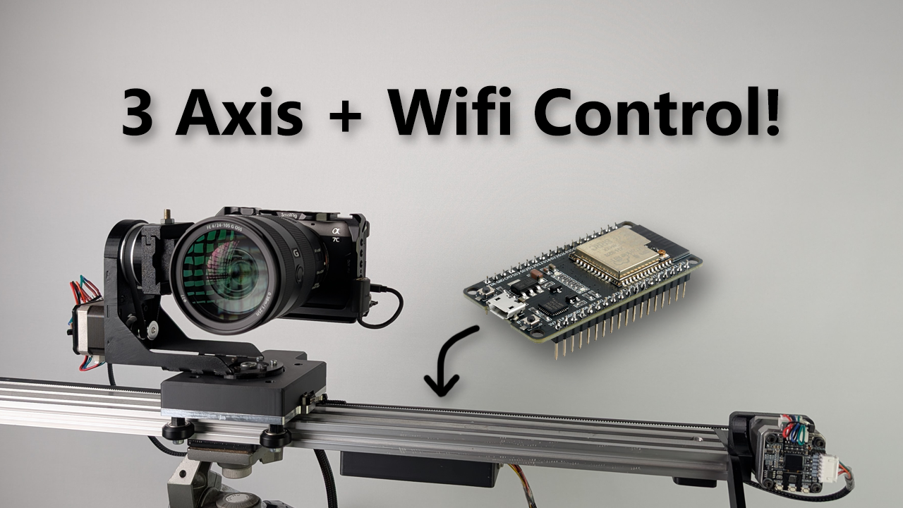
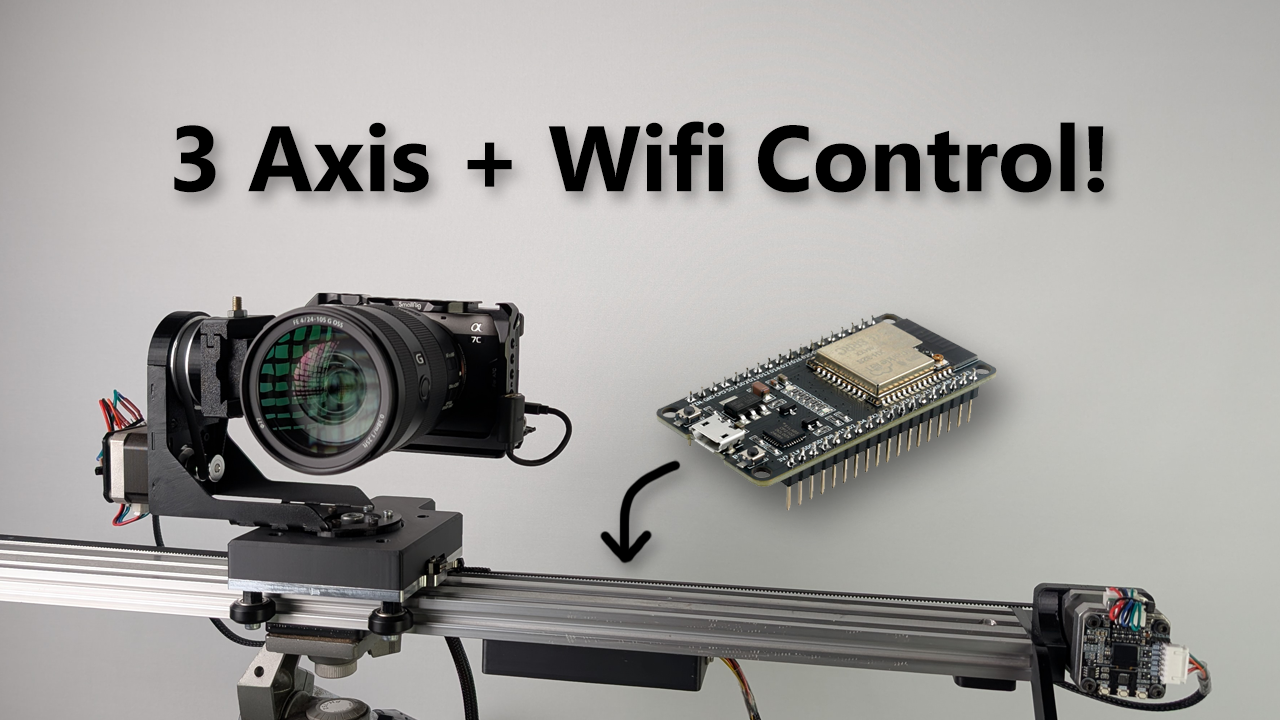
Creator thumbnail showing the three-axis camera sliderCreator thumbnail showing the three-axis camera slider · Daniel McKenzie / CNCDan ↗
PHYSICAL BUILD10 key parts or groups
No.Source specification
01ESP32 development board and 5 V regulator
02Three NEMA 17 34 mm stepper motors
03Three compatible step and direction stepper drivers selected by the builder
04V-slot 2060 extrusion
0520T and 80T GT2 pulley hardware
06Printed carriage
07Laser-cut tripod mount plate and folded/welded tilt bracket
08Machined aluminium linear slider plate
09M2
10Driver-specific power supply
Full source specifications
  1. ESP32 development board and 5 V regulator
  2. Three NEMA 17 34 mm stepper motors
  3. Three compatible step and direction stepper drivers selected by the builder
  4. V-slot 2060 extrusion, V wheels, bearings and GT2 belts
  5. 20T and 80T GT2 pulley hardware, including source-required machining on the 80T route
  6. Printed carriage, motor mounts, covers, electronics enclosure, quick-release pieces and spacers
  7. Laser-cut tripod mount plate and folded/welded tilt bracket
  8. Machined aluminium linear slider plate
  9. M2, M3, M5, M6 and M8 fasteners, T-nuts, springs and small mechanical hardware
  10. Driver-specific power supply, connectors and wiring selected to match the chosen motors and drivers
TOOLS / PROCESSES5 involved
  • 3D printer or print service
  • Laser cutting
  • Metal folding and welding
  • CNC machining and tapping
  • Soldering and electronics tools
The real-world workYOU STILL HAVE TOThe real-world work
  • Choose whether the required printing, laser cutting, folding, welding and machining will be done in-house or outsourced
  • Fabricate and inspect the printed and metal parts, including tapped holes and modified pulley features where the source requires them
  • Choose three compatible step and direction drivers plus a suitable power route, then verify current, voltage, grounding and wiring against the actual hardware
  • Assemble and align the linear, pan and tilt mechanics so belts, bearings and wheels move freely without excessive play
  • Support the rail and camera securely with suitable tripods, mounting plates and a reliable quick-release arrangement
  • Set real travel limits and motor configuration from physical measurements rather than copying defaults
  • Commission the rig unloaded and at low speed, then use a low-consequence test mass before fitting valuable camera equipment
  • Keep WiFi credentials private, replace weak defaults where practical and avoid exposing the controller to an untrusted network
THE BUILD SEQUENCE

How it comes together

1Preparation

  1. Decide the fabrication route first

    Review every printed, laser-cut, folded, welded and machined part before buying electronics. Get real fabrication access or quotes because the custom metal work can dominate the first-build cost.

    AI + YOU
  2. Source the commodity motion hardware

    Use the source BOM for motors, bearings, V wheels, belts, pulleys, extrusion, ESP32, regulator and fasteners. Keep the three stepper drivers separate because the creator deliberately leaves that choice open.

    AI + YOU
  3. Print and fabricate the custom parts

    Print the published parts with the required strength, then laser cut, fold, weld, machine and tap the metal pieces to the drawings. Do not assume a cosmetic print setting is sufficient for load-bearing parts.

    YOU

2Build and assembly

  1. Assemble and align the three axes

    Build the slider carriage, pan axis and tilt axis while checking bearing preload, belt tracking, pulley alignment and free movement. Fix mechanical binding before adding software tuning.

    YOU
  2. Choose and wire the drive electronics

    Select three step and direction drivers and a power supply that match the actual motors and operating current. Verify the selected driver datasheets, wiring and thermal requirements rather than copying the original driver choice blindly.

    AI + YOU
  3. Configure motion from measurements

    Set the real linear travel, steps, microsteps, gear ratios, GPIO and network configuration. The source notes that incorrect ESP32 pin choices can affect booting, so prove the electronics before enclosing them.

    AI + YOU

3Configure and test

  1. Commission without a valuable camera

    Run homing, direction, stopping, keyframe and slow-move tests unloaded first. Then use a safe test mass to prove supports, repeatability, acceleration and clearances before fitting camera equipment.

    YOU
  2. Validate the real shooting workflow

    Program representative multi-keyframe and timelapse moves, watch for cable snagging, support flex, missed steps and camera clearance, and keep a human able to stop the rig whenever people or valuable equipment are nearby.

    YOU

Benchmark this project

Use the ESP32 3-Axis Camera Slider prompt. Compare what different models deliver, then add what happened when you tried it.

Try this benchmark
View the project prompt

CAIBI adaptation · Prompt 1.0 · Project source

Open and copy prompt →

Benchmark results 0

No reviewed results yet for ESP32 3-Axis Camera Slider. Add the first result →

AI IN THIS PROJECT

Get AI help on this build

CAIBI · AI CAN HELP

AI can help with

  • Turn the source BOM and CAD set into a staged sourcing and fabrication checklist
  • Help compare fabrication routes when you provide real machine, material or supplier constraints
  • Review ESP32 configuration for travel, microsteps, gearing, GPIO and WiFi without inventing missing hardware limits
  • Help adapt the web interface, keyframe logic and motion code for a documented camera workflow
  • Diagnose motion, direction, acceleration and repeatability problems from measured behaviour and configuration
  • Review the selected stepper-driver datasheet and wiring plan while leaving current, voltage and physical inspection to the builder
  • Help create a low-consequence commissioning plan before a valuable camera is fitted
CAIBI · AI CAN'T DO

You still need to

  • Choose whether the required printing, laser cutting, folding, welding and machining will be done in-house or outsourced
  • Fabricate and inspect the printed and metal parts, including tapped holes and modified pulley features where the source requires them
  • Choose three compatible step and direction drivers plus a suitable power route, then verify current, voltage, grounding and wiring against the actual hardware
  • Assemble and align the linear, pan and tilt mechanics so belts, bearings and wheels move freely without excessive play
  • Support the rail and camera securely with suitable tripods, mounting plates and a reliable quick-release arrangement
  • Set real travel limits and motor configuration from physical measurements rather than copying defaults
  • Commission the rig unloaded and at low speed, then use a low-consequence test mass before fitting valuable camera equipment
  • Keep WiFi credentials private, replace weak defaults where practical and avoid exposing the controller to an untrusted network
Original source AI use and prompts
SOURCEThe original project does not publish an AI prompt

The prompts below are CAIBI helpers for this build. They are not presented as instructions from the creator.

CAIBI STARTING PROMPTS

Copy a prompt for this build

Each prompt tells AI to keep the original project source as the reference and to flag anything you must verify on the real build.

Ways to take it further
AFTER THE FIRST BUILD

Ways to take it further

Source 3-axis slide, pan and tilt buildShorter or longer linear extrusion after recalculating real travelAlternative step and direction drivers3D-printed low-load pulley experiment instead of machined pulley
More routes and resources
OTHER WAYS TO GET THERE

You do not have to follow one route.

REVIEWED RESOURCES

Useful places beyond the main source

SOURCE · CAIBI · BUILDERS

What supports the verdict

SOURCEDaniel McKenzie / CNCDan

The project is current and unusually well documented for a new maker build. The repository was created and pushed in March 2026 and includes the BOM, complete assembly CAD, individual fabrication files and source code. Hackaday and Adafruit independently covered the finished project in May 2026. CAIBI found strong evidence that the creator built and tested the rig, but not an independent builder replication, so the assessment remains Moderate rather than Strong.

Open source ↗
CAIBIWORTH CONSIDERING

This is a serious custom motion project rather than an electronics demo. It can produce programmable slide, pan and tilt moves with up to five keyframes and a browser-based controller, while keeping the mechanics, gearing and code open to modification. The case is strongest if you already have fabrication access, spare motion hardware or a reason to tailor the rig around a specific camera workflow.

Evidence: Moderate

Leave a build review
HAVE YOU MADE THIS?

Leave a build review.

First-hand evidence improves the assessment
What we want to know

What happened when you actually tried to make it.

  • Did it work?
  • Actual time and cost
  • What did you change?
  • What was harder than the source suggested?
  • Would you build it again?